

Commissioning and Field Testing of Power Cables: Ensuring Reliability Before Energization
/
This article draws on technical material presented by the Kinectrics technical team during Cable IQ 2026, a Power Knowledge Sessions event hosted by Composite Power Group in Calgary on November 5, 2026.

A newly installed power cable may have successfully passed factory testing, been manufactured to recognized industry standards, and been installed according to approved procedures. Yet before it can be safely placed into service, one critical question remains: Is the completed cable system ready for energization?
Commissioning and field testing provide an important opportunity to identify defects introduced during transportation, handling, installation, jointing, or termination. These activities help verify that the completed cable system can withstand its intended electrical stresses and provide valuable information about its condition before it enters service.
For utilities, engineers, electrical contractors, and asset managers, understanding the different testing methods and their limitations is essential. No single test can identify every potential defect, and selecting an inappropriate testing method may provide false confidence in the condition of an installation.
This article explores the principles of cable commissioning, the differences between dielectric withstand testing and diagnostic testing, and the engineering considerations involved in evaluating newly installed medium-voltage (MV), high-voltage (HV), and extra-high-voltage (EHV) cable systems.
1. Why Commissioning Testing Matters
Power cable reliability depends on the integrity of the complete installed system, not simply the cable as it leaves the manufacturing facility. A finished installation typically includes the cable itself, joints, terminations, metallic screens or sheaths, grounding and bonding arrangements, and associated electrical equipment. Each component introduces potential sources of failure. Even when the cable has been manufactured correctly, installation activities may introduce defects such as:
Mechanical damage to insulation or metallic shielding
Contamination during joint or termination preparation
Improperly installed stress-control components
Voids or irregularities at accessory interfaces
Damage caused by excessive pulling tension or bending
Compromised outer jackets or moisture barriers
Incorrect grounding or bonding connections
Some defects may be severe enough to cause immediate electrical breakdown. Others may remain undetected until the cable has operated for an extended period. Commissioning testing helps identify problems before the system is placed into service, when corrective action may be less disruptive than responding to an unexpected outage.
Factory Testing vs. Field Testing
Factory testing takes place under controlled conditions, often using specialized equipment and carefully managed electrical environments. Field testing takes place after installation, where the completed cable system may extend over considerable distances and operate in an environment containing electrical interference. The objectives and practical limitations are therefore different. Factory testing verifies the manufactured product against defined requirements. Field commissioning evaluates the completed installation, including the effects of handling, installation, and accessory assembly.
Passing factory tests does not eliminate the need to evaluate the completed cable system before energization.
2. Defining the Objectives of Commissioning
Before selecting a test method, engineers should establish what the commissioning program is intended to demonstrate. A typical program may have several objectives.
Verify Insulation Integrity
The cable system must be capable of withstanding the electrical stresses associated with its intended operating conditions.
Identify Installation-Related Defects
Commissioning should help identify problems introduced during cable pulling, handling, jointing, or termination.
Verify Jacket and Sheath Integrity
Damage to the outer protective system can allow moisture ingress or create other long-term reliability concerns.
Evaluate Accessories
Joints and terminations are critical interfaces where improper workmanship or contamination may introduce localized defects.
Establish Baseline Information
Diagnostic measurements collected during commissioning can provide useful reference information for future testing and condition assessment.
These objectives are related but not identical. A test designed primarily to demonstrate insulation withstand capability may not provide detailed information about the location or nature of a defect. Similarly, a diagnostic measurement may reveal evidence of deterioration without demonstrating that the cable can withstand a specified electrical stress. An effective commissioning program recognizes these differences.
3. Dielectric Withstand Testing: Demonstrating Electrical Strength
Dielectric withstand testing, commonly referred to as hipot testing, is a fundamental method used during cable commissioning. The principle is straightforward: a specified test voltage is applied to the insulation system for a defined period. If the system withstands the applied electrical stress without breakdown, it satisfies the withstand criterion for that test.
What Does a Withstand Test Demonstrate?
A withstand test evaluates whether the cable system can withstand the specified electrical stress under the test conditions. It can expose defects that are sufficiently severe to cause failure under the applied voltage. However, a successful test does not prove that the cable is free from all defects. A localized imperfection may survive the test while continuing to produce electrical activity that contributes to deterioration during future operation.
Pass/Fail Testing
Traditional withstand testing is fundamentally a pass/fail assessment. The cable either withstands the specified voltage for the required duration or experiences electrical breakdown. This provides a clear acceptance criterion but limited information about defects that do not cause failure.
Limitations of Withstand Testing
A withstand test generally does not identify the precise location or nature of a defect unless additional diagnostic or fault-location methods are employed. Furthermore, the electrical stress applied during testing must be appropriate for the cable's insulation system, voltage class, and condition. An excessively severe test may impose unnecessary stress, particularly on aged or degraded insulation. For these reasons, test parameters should be established using applicable standards, manufacturer recommendations, and project-specific engineering requirements.
4. Understanding AC, VLF, and DC Testing
Different electrical waveforms can be used to evaluate cable insulation. The choice depends on the cable construction, voltage class, test objective, and available equipment.
Power-Frequency AC Testing
Alternating-current testing at or near the normal operating frequency provides an electrical stress waveform representative of service conditions. It is particularly relevant to high-voltage cable systems. However, long cables have substantial capacitance, which can require large amounts of reactive power during testing. This makes conventional power-frequency testing equipment impractical for some field applications.
Very Low Frequency (VLF) Testing
VLF testing applies alternating voltage at a frequency substantially below normal power frequency. A commonly used test frequency is 0.1 Hz, although other frequencies may be used depending on the equipment and procedure. Because the capacitive current required to energize a cable decreases with frequency, VLF testing can reduce the power requirements of field testing equipment. This makes VLF testing particularly useful for many medium-voltage cable applications. However, VLF testing does not replicate all electrical characteristics of normal power-frequency operation. Test results must therefore be interpreted according to the applicable waveform and test procedure.
DC Testing
Direct-current testing has historically been used for certain cable insulation systems. However, DC withstand testing is generally not recommended as a routine commissioning method for modern extruded polymeric insulation systems, such as XLPE, because the resulting electrical stress distribution and potential space-charge effects differ from those under normal AC operation. The suitability of DC testing depends on the cable type and intended test. DC methods remain relevant for certain jacket and sheath integrity tests.
Selecting the Appropriate Method
No single waveform is universally suitable for every cable system. The correct approach depends on the insulation material, operating voltage, cable length, and objective of the test. For example, a medium-voltage distribution cable may be evaluated using a VLF-based commissioning procedure, while an extra-high-voltage transmission installation may require a different AC testing arrangement.
5. Partial Discharge Testing: Identifying Localized Insulation Defects
Partial discharge (PD) testing provides a diagnostic perspective that differs fundamentally from conventional withstand testing. Partial discharge is a localized electrical discharge that does not completely bridge the insulation between conductors. It may occur within voids, at insulation interfaces, or around defects where the local electric field becomes sufficiently intense.
How Partial Discharge Develops
In a properly designed cable system, electrical stress is controlled through the insulation and shielding geometry. However, defects such as voids, contamination, protrusions, or poorly prepared accessory interfaces can create localized regions of elevated electrical stress. When the local electric field exceeds the electrical strength of the affected region, partial discharge may occur. Repeated discharge activity can contribute to progressive insulation damage.
Common Sources of Partial Discharge
Potential sources include:
Voids within insulation
Contamination at insulation interfaces
Damaged semiconductive shielding
Improperly installed joints
Defective termination stress-control components
Mechanical damage introduced during installation
In newly installed cable systems, accessory workmanship is a particularly important consideration. The cable insulation may be in excellent condition, while a joint or termination contains a localized defect introduced during assembly.
What Can PD Testing Reveal?
Partial discharge measurements can provide information about localized electrical activity. Depending on the test method and measurement arrangement, diagnostic analysis may help determine:
Whether discharge activity is present
The voltage at which activity begins
How discharge activity changes with applied voltage
Whether the activity is associated with a particular location
Whether further investigation is warranted
However, not every defect produces detectable partial discharge under the conditions of a particular test. The absence of measured PD activity should therefore not be interpreted as proof that the cable system contains no defects.
6. Partial Discharge Inception and Extinction Voltages
Two useful concepts in partial discharge testing are partial discharge inception voltage (PDIV) and partial discharge extinction voltage (PDEV).
Partial Discharge Inception Voltage
PDIV is the voltage at which sustained partial discharge activity first becomes detectable as the applied test voltage increases, according to the measurement procedure.
Partial Discharge Extinction Voltage
PDEV is the voltage below which sustained partial discharge activity ceases as the applied voltage decreases. These measurements can help characterize the electrical behaviour of a defect. For example, discharge activity that begins at relatively low electrical stress may be more concerning than activity observed only at substantially higher test voltages. However, interpretation requires knowledge of the cable system, test waveform, measurement sensitivity, and applicable acceptance criteria. A single inception-voltage measurement should not be used in isolation to determine whether a cable system is suitable for service.
7. Monitored Withstand Testing: Combining Strength and Diagnostics
Traditional withstand testing and partial discharge testing answer different questions. A withstand test evaluates whether the insulation survives a specified electrical stress. Partial discharge testing examines localized electrical activity that may indicate defects. Monitored withstand testing combines elements of these approaches. During a monitored withstand test, the cable is subjected to a specified voltage while diagnostic measurements are collected.
Why Monitoring Adds Value
Consider a cable system that successfully withstands the applied voltage but exhibits increasing partial discharge activity during the test. A conventional pass/fail withstand assessment may indicate that the system passed. However, the diagnostic measurements may suggest that a localized defect requires further investigation. This additional information can help engineers distinguish between a system that simply survived the test and one that shows evidence of potentially concerning electrical activity.
Can Monitoring Prevent Cable Failure?
Monitoring may provide warning signs of developing problems, but it cannot guarantee that a breakdown will be prevented. Some defects may progress rapidly, and the relationship between measured activity and failure risk is not always straightforward. Nevertheless, monitored testing can provide a more informative assessment than a withstand test alone.
The value of monitored withstand testing lies in combining evidence of electrical strength with information about potentially damaging insulation activity.
8. Tan Delta Testing: Evaluating Dielectric Losses
Tan delta testing is another diagnostic technique used to evaluate cable insulation. Unlike partial discharge testing, which focuses on localized electrical activity, tan delta measurements examine the dielectric losses of the insulation system.
Understanding Dielectric Loss
An ideal insulating material would behave primarily as a capacitor, storing and releasing electrical energy with minimal loss. Real insulating materials exhibit some energy dissipation. The dielectric loss factor, commonly expressed as tan delta, describes the relationship between the resistive and capacitive components of the insulation response. Changes in dielectric losses can provide information about the insulation condition.
What Can Tan Delta Reveal?
Tan delta testing can be useful in evaluating broader insulation deterioration, particularly in certain medium-voltage cable systems. For example, water-tree aging in polymeric insulation can affect dielectric losses. Measurements at different applied voltages may reveal changes in insulation behaviour.
Tan Delta Tip-Up
One commonly used diagnostic concept is the tan delta tip-up. This refers to the change in measured tan delta between different test voltage levels. A significant change may indicate voltage-dependent dielectric behaviour requiring further evaluation. However, interpretation depends on the insulation material, cable condition, test method, and applicable diagnostic criteria.
Limitations of Tan Delta Testing
Tan delta measures the overall dielectric response of the tested system. A small localized defect may have little influence on the aggregate measurement. Consequently, tan delta testing may not reliably detect certain joint or termination defects that can be identified through partial discharge measurements. This distinction is particularly important during commissioning, where installation-related defects may be localized rather than distributed throughout the insulation.
9. Why No Single Test Is Sufficient
Withstand testing, partial discharge testing, and tan delta testing provide different information about cable condition. Their capabilities overlap in some areas, but they are not interchangeable.
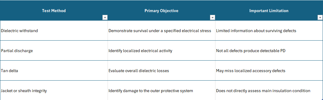
A comprehensive commissioning program may combine several methods depending on the cable system and project requirements. For example, a newly installed medium-voltage cable may require insulation withstand testing, jacket verification, and selected diagnostic measurements. A high-voltage transmission system may require a different combination of tests, reflecting its construction, accessories, voltage class, and consequences of failure. The correct testing program should be established before commissioning begins.
10. Jacket and Sheath Integrity Testing
The outer jacket and metallic sheath systems are important elements of cable reliability. They protect the cable from moisture, mechanical damage, and environmental exposure. Damage to these protective components may not immediately affect the main insulation, but it can create conditions that contribute to future deterioration.
Why Jacket Testing Matters
During installation, cable jackets may be damaged by:
Abrasion against conduit surfaces
Sharp edges or installation equipment
Excessive mechanical pressure
Improper handling
Damage during joint or termination preparation
A compromised jacket may allow moisture to reach metallic components or other protective layers.
Testing Approaches
Depending on the cable construction, jacket integrity may be evaluated using an appropriate electrical test between the metallic screen or sheath and an external reference electrode. The test method and voltage must be compatible with the cable design. Not all cable constructions are suitable for the same jacket testing procedures. For this reason, the manufacturer and applicable standards should guide the selection of test parameters.
Long-Term Implications
Identifying jacket damage before energization provides an opportunity to investigate and repair defects before the cable enters service. This is especially important for underground transmission systems where later access may be difficult and expensive.
11. Field Testing Challenges: Noise, Distance, and Measurement Sensitivity
Field commissioning is inherently more challenging than laboratory testing. A manufacturing facility may use specialized shielded environments to minimize electrical interference. Field installations operate in much less controlled conditions.
Electrical Noise
Nearby energized equipment, switching activity, communication systems, and other sources can introduce electrical signals that interfere with diagnostic measurements. In partial discharge testing, distinguishing genuine discharge activity from external noise is essential.
Cable Length
Long cable systems introduce additional challenges. High-frequency diagnostic signals can attenuate and disperse as they travel through the cable. A discharge occurring far from the measurement point may produce a weaker or distorted signal.
Sensor Placement
The location and configuration of diagnostic sensors influence measurement sensitivity. For long or complex cable systems, multiple measurement locations may be necessary to obtain useful diagnostic information.
Specialist Interpretation
Collecting diagnostic data is only part of the process. Experienced personnel must evaluate the results, distinguish genuine defects from interference, and consider the limitations of the measurement system. This is particularly important in high-voltage applications where the consequences of an undetected defect can be substantial.
A technically sophisticated test is only as useful as the quality of its execution and interpretation.
12. Testing Individual Circuits vs. Multiple Circuits Together
Testing arrangements can influence both the sensitivity and usefulness of diagnostic results. In some installations, several cable circuits may be electrically connected during testing. Although this may appear efficient, it can introduce complications.
Reduced Diagnostic Sensitivity
When multiple circuits are tested together, their combined electrical characteristics can affect the measurement response. A localized defect in one circuit may become more difficult to detect or interpret.
Difficulty Identifying the Defective Circuit
If abnormal activity is detected, determining which cable contains the defect may require additional investigation. This can complicate fault localization and corrective action.
Testing Strategy
Where practical and technically appropriate, testing circuits individually can provide clearer diagnostic information. However, the final arrangement depends on the system configuration, available equipment, and commissioning objectives. The testing plan should account for these considerations before fieldwork begins.
13. Commissioning New Cables vs. Testing Aging Cable Systems
Commissioning and maintenance testing share some methods, but their objectives are different.
Newly Installed Cable Systems
Commissioning focuses primarily on identifying manufacturing, transportation, installation, and accessory-related defects before energization. The cable insulation is expected to be in relatively good condition, and significant aging mechanisms should not yet be present. Localized workmanship defects are therefore an important concern.
Aging Cable Systems
Condition assessment of existing cable networks involves a broader range of potential deterioration mechanisms.
These may include:
Water-tree development
Thermal aging
Electrical treeing
Accessory deterioration
Environmental damage
Previous operating stresses
Testing an aged cable also requires considering that elevated test stresses could contribute to the failure of already-weakened insulation.
Different Objectives Require Different Strategies
A commissioning program may prioritize demonstrating electrical withstand capability and identifying localized installation defects. A maintenance program may prioritize estimating condition, identifying deterioration trends, and determining whether an asset should remain in service. The same diagnostic result may therefore have different implications depending on the cable's age, construction, and operating history.
14. Interpreting Test Results and Making Engineering Decisions
The ultimate objective of commissioning is not simply to collect measurements. It is to determine whether the cable system is suitable for energization and whether corrective action is required.
When a Cable Passes All Tests
Successful results provide evidence that the system satisfies the specified commissioning requirements. However, they do not guarantee that the cable will never fail in the future. The results should be interpreted within the limitations of the test methods.
When a Diagnostic Result Is Abnormal
An abnormal measurement does not automatically mean that the entire cable must be replaced. Further investigation may identify a localized problem, such as a defective joint or termination. In some cases, targeted repair and subsequent retesting may provide an appropriate solution.
When a Withstand Test Fails
A breakdown during withstand testing requires fault investigation. The affected section or component must be identified, and the cause should be evaluated before repair or replacement. Depending on the circumstances, physical examination and electrical measurements may help distinguish between installation damage, accessory defects, and cable insulation problems.
Documenting the Results
A commissioning report should clearly identify:
The cable system and circuits were tested
The test methods and equipment used
Applied voltage, waveform, frequency, and duration
Measurement conditions and limitations
Diagnostic results
Applicable acceptance criteria
Any abnormal observations
Corrective actions and retesting
Final engineering conclusions
These records can provide valuable baseline information for future asset management.
15. Developing an Effective Commissioning Strategy
A successful commissioning program begins during project engineering, not after installation is complete. The testing requirements should be coordinated with the cable manufacturer, the utility, the installation contractor, and the testing organization.
Step 1: Define the System
Identify the cable voltage class, insulation type, construction, length, accessories, and bonding configuration.
Step 2: Establish the Testing Objectives
Determine whether the program is intended to verify withstand capability, identify localized defects, evaluate jacket integrity, or establish baseline diagnostic information.
Step 3: Select Appropriate Methods
Choose testing techniques suited to the cable system and the defects of concern.
Step 4: Establish Test Parameters
Define the required voltage, waveform, frequency, duration, and acceptance criteria using applicable standards and manufacturer recommendations.
Step 5: Evaluate Field Conditions
Consider cable length, electrical interference, equipment capabilities, sensor placement, and site access.
Step 6: Perform and Document Testing
Use qualified personnel, appropriate equipment, and consistent procedures.
Step 7: Investigate Abnormal Results
Determine whether additional testing, fault localization, repair, or replacement is necessary.
Step 8: Establish Readiness for Energization
Review the completed commissioning evidence and confirm that the system satisfies the applicable acceptance requirements.
Following this process helps ensure that commissioning is a structured engineering activity rather than a collection of disconnected tests.
Conclusion: Testing for Confidence, Not Just Compliance
Commissioning and field testing are essential safeguards in the transition from cable installation to energized operation. A cable system may be manufactured correctly and installed with care, yet still contain defects that compromise long-term reliability. Dielectric withstand testing provides evidence of electrical strength. Partial discharge measurements can reveal localized insulation activity. Tan delta testing offers insight into broader dielectric conditions, while jacket testing helps verify the integrity of protective components. Each method provides different information and has its limitations. For utilities and engineers, the challenge is to select the right combination of tests, apply appropriate electrical stresses, and interpret the results in the context of the complete cable system. The objective is not simply to obtain a passing test report, but to make an informed engineering decision about whether the installation is ready for service.
The key takeaway is simple: effective commissioning combines appropriate testing methods, qualified interpretation, and clear acceptance criteria to establish confidence in the reliability of a newly installed cable system.
