

Understanding Power Cable Design: Materials, Insulation, Shielding, and System Reliability
/This article draws on technical material presented by Polyxeni Karavida, Design Manager at Hellenic Cables, during Cable IQ 2026, a Power Knowledge Sessions event hosted by Composite Power Group in Calgary on November 5, 2026.

Modern power cables are complex, carefully engineered systems designed to deliver electrical energy safely and reliably over decades of operation. While a cable may appear relatively simple from the outside, its performance depends on the interaction of multiple components, each serving a specific electrical, mechanical, or protective function.
This paper is intended to describe what belongs in a power cable specification and why each cable component matters, including the materials, insulation and shielding that determine system reliability.
From conductor selection and insulation materials to metallic shielding, water protection, and manufacturing quality, every design decision influences the cable's performance, service life, and suitability for its intended application.
Understanding these elements is essential for utilities, engineers, and project managers responsible for specifying, procuring, and maintaining medium-voltage (MV), high-voltage (HV), and extra-high-voltage (EHV) cable systems.
Understanding the Anatomy of a Power Cable
A shielded cable contains two electrical boundaries: the central conductor and the surrounding metallic screen or sheath. The main insulation withstands the voltage between them. Semiconductive layers create smooth interfaces on either side of that insulation, while water blocking and the jacket protect the assembly from its environment. The layers have distinct jobs, but their dimensions, materials and interfaces must work together.
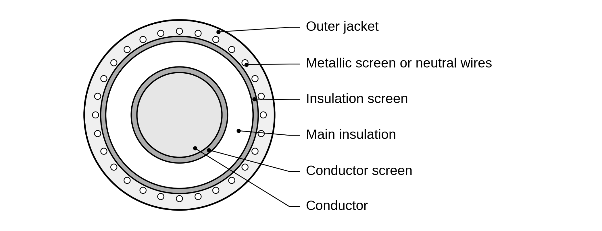
Figure 1. A shielded single-core cable with a wire metallic screen. Schematic only; additional tapes, barriers and sheath arrangements vary by design.
For example, changing conductor construction can alter its diameter and the connector required. A different insulation wall changes electrical stress, heat flow and accessory fit. A change to the metallic layer can alter fault capacity, moisture protection and losses. These interactions explain why a cable cannot be specified successfully as a set of unrelated material choices.
Medium voltage and transmission cable designs
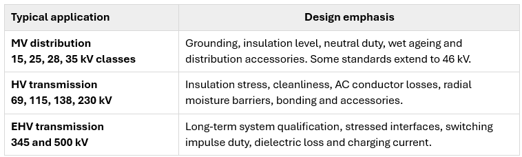
The same basic anatomy appears at several voltage levels, but the design emphasis changes. MV distribution commonly uses standardized cable classes, insulation walls and separable connectors. HV and EHV land systems more often require an engineered combination of cable, joints, terminations, moisture barriers and sheath bonding. The voltage labels vary among standards; the actual rating and qualification scope define the application.
Conductor Selection and Construction
Conductor selection begins with the load the circuit must carry and the faults it must withstand within the cable system’s temperature limits. Ampacity is the allowable current under stated installation and temperature conditions. The objective is the lowest total cost for the required electrical performance, with utility standardization included in the comparison. Purchase, installation, energy losses and ongoing support, including connectors and spare inventory, all contribute to that cost.
Copper’s higher conductivity allows a smaller conductor area for a specified resistance. That can be valuable where duct space, cable diameter or accessory dimensions constrain the route. Aluminum is lighter and can reduce conductor material cost, but normally needs a larger area for comparable resistance. Where the route and accessories accommodate that size, aluminum can provide the required electrical performance economically.
Both materials can meet the same circuit duty when appropriately sized. A fair comparison uses the same load duty and installation conditions, then evaluates the total cost of meeting the required ampacity and fault performance. If a material or size change needs different connectors, tools or spare stock, its expected savings also need to justify those changes to the utility’s standard cable family.
After material and area, conductor construction affects how the cable fits and handles. Solid, stranded, compressed and compact conductors produce different diameters and flexibility. Compression and compaction reduce spaces between strands. The finished conductor still has to match its connector and preparation method, so a common nominal size alone does not establish accessory compatibility.
Why skin and proximity effects matter
For large conductors, adding metal does not produce a proportionate improvement in AC performance. Current is distributed unevenly: skin effect shifts current density toward the surface, while proximity effect redistributes it in response to neighbouring conductors’ fields. Both can increase AC resistance and reduce the benefit of added area. Skin depth provides a useful scale for the first effect. With electrical resistivity ρ in Ω·m, frequency f in Hz and permeability μ in H/m, the result below is in metres.
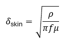
At 60 Hz and 20 °C, skin depth is about 8.5 mm in copper and 10.9 mm in aluminum. These values use representative conductor resistivities of 1.7241 × 10⁻⁸ and 2.8264 × 10⁻⁸ Ω·m, respectively, with μ ≈ 4π × 10⁻⁷ H/m. A solid round 1,200 mm² conductor has a radius of about 19.5 mm. The core still carries current, but added metal is used less effectively by AC than by DC. This becomes important in large HV and EHV conductors.
Milliken construction addresses these losses by improving current distribution in a large conductor. Shaped sectors are electrically separated and laid helically along the cable; some designs also give individual strands an insulating treatment. Sector construction and lay reduce transverse currents that contribute to AC loss. Sector forming, separation and assembly add manufacturing complexity. Their value therefore depends on the reduction in AC resistance and operating temperature, together with a qualified connector arrangement.
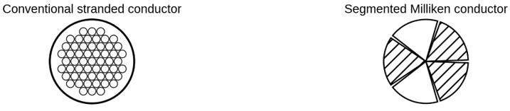
Figure 2. Conventional stranded and segmented Milliken conductors. The drawing is schematic; sector count and strand treatment vary.
Resistance losses and temperature
Electrical losses are an operating expense and heat that the cable must release. Conductor resistance increases with temperature, so the comparison needs a common temperature basis. The usual linear correction uses R₂₀, the DC resistance per unit length at 20 °C; α₂₀, the temperature coefficient in 1/°C; and Δθ, the temperature rise above 20 °C. All resistance values use the same length basis. Skin and proximity factors yₛ and yₚ are dimensionless and depend on the offered construction and phase arrangement.

For a balanced three-phase circuit with one cable per phase, I is the RMS current in amperes in each phase cable and L is route length. Pcond is the total loss in the three phase conductors. Using resistance in Ω/km with L in kilometres gives watts; Ω/m with metres gives the same result.
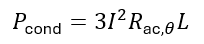
At 1,000 A over a 5 km route, illustrative AC resistances of 0.018 and 0.016 Ω/km at the same operating temperature produce 90 and 80 kW per phase, respectively. The three-phase totals are 270 and 240 kW, a difference of 30 kW. That difference affects energy use and heat rejection. Comparing offered AC resistance at a common temperature and formation therefore gives useful information beyond conductor area or purchase price.
Insulation Materials and Voltage Requirements
Insulation selection balances the required electrical withstand and ageing performance against cable size, heat flow, accessory fit and cost. The required withstand follows the system’s operating voltage and overvoltage exposure. The material and wall thickness then form part of a qualified construction. Its long-term performance depends on the compound, adjacent screens, manufacturing quality, temperature and moisture exposure. XLPE, TR-XLPE and EPR are established material families that meet different service needs; the family name alone does not define the finished cable’s performance.
XLPE. Crosslinked polyethylene, or XLPE, combines useful thermal and mechanical properties with low dielectric loss. The low loss becomes particularly valuable on long energized HV and EHV circuits. Its performance still depends on clean material, controlled interfaces and the moisture protection appropriate to the application.
TR-XLPE. Tree-retardant XLPE is formulated to resist water-tree development in wet MV service. Water-tree resistance addresses deterioration associated with moisture, electric field and time. It does not remove the need for sound interfaces or prevent electrical treeing from every sharp defect.
EPR. Ethylene propylene rubber compounds can provide flexibility and wet-ageing performance that suit distribution or industrial routes. Their dielectric loss, thermal properties and preparation characteristics depend on the formulation. Flexibility is useful where handling is difficult, but the complete cable and accessory system still has defined bending and temperature limits.
A good material choice therefore compares the offered compound’s ageing evidence, dielectric loss, thermal performance, dimensions and accessory compatibility. A higher declared temperature rating is a qualified operating limit, rather than a promise of equal service life at every temperature below that limit.
RMS voltage, insulation level and BIL
The insulation level needs to reflect the voltage across the insulation and how long an abnormal voltage can persist. System nominal voltage is normally stated as line-to-line RMS, while an individually screened cable is stressed between conductor and screen. In a balanced grounded system with the screen near earth potential, normal RMS and sinusoidal peak voltages are related as follows.

For a nominal 25 kV line-to-line RMS system, normal line-to-ground voltage is approximately 14.43 kV RMS, with a sinusoidal crest of 20.41 kV.

Grounding changes the voltage that healthy phases experience during an earth fault. On an isolated-neutral system, that voltage can rise toward the line-to-line value. Load rejection or resonance can also produce temporary power-frequency overvoltage. Insulation selection therefore uses maximum operating voltage and credible overvoltage magnitude and duration, including the protection’s clearing time.
The usual MV application categories link 100% insulation level to rapid earth-fault clearing within one minute and 133% to conditions where clearing within one hour is assured. Longer fault operation requires the applicable 173% provisions or another qualified design basis. These are application categories, separate from concentric-neutral size and from impulse withstand. The percent label is not an exact wall-thickness multiplier.
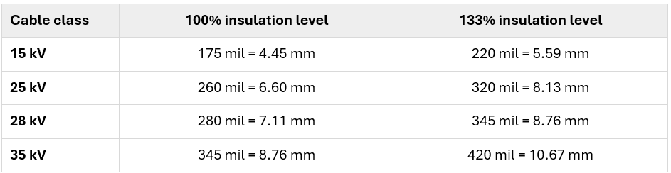
Representative conventional MV walls, excluding semiconductive screens. One mil is 0.0254 mm. The governing standard, conductor size, material and wall design establish nominal and minimum requirements.
Basic lightning impulse insulation level, or BIL, is a peak-kV withstand rating for a prescribed lightning impulse, nominally 1.2/50 μs. Switching can also create transient stress, but BIL does not establish capability for every switching waveform or for sustained overvoltage. EHV systems also consider slower switching impulse duty. Arrester protective level, connections and wave reflections determine the margin to withstand. There is no single Canadian BIL multiplier or direct conversion from BIL to millimetres of insulation.
Controlling Electrical Stress with Semiconductive Screens
Insulation and semiconductive screens perform different parts of the same task. The insulation withstands the electric field, while the screens establish smooth electrical boundaries. Their interaction explains why material strength and wall thickness are only part of the design: additional bulk insulation cannot compensate for every damaged or contaminated interface.
The semiconductive screens are polymer compounds made conductive, commonly with carbon black. The conductor screen covers strand contours with a smooth boundary near conductor potential. The insulation screen establishes the corresponding outer boundary near metallic-screen potential. Their conductivity spreads potential around each surface; it does not make the radial field uniform through the insulation.
Electrical stress is the electric field in the insulation, commonly expressed in kV/mm. It describes how quickly voltage changes with distance. Unlike the approximately uniform field between broad parallel plates, the field in cylindrical cable insulation is strongest close to the conductor and decreases outward.
For smooth concentric boundaries and homogeneous insulation, a is the radius to the outside of the conductor screen and b is the radius to the inside of the insulation screen. At a point within the wall, r lies between a and b. Vcs is conductor-to-screen voltage, and ln denotes the natural logarithm. With RMS kV and millimetres, the expressions give RMS kV/mm; peak voltage gives peak field. Eavg is an average along the radial thickness.

In an illustrative balanced 138 kV line-to-line RMS system, Vcs = 79.67 kV RMS, a = 24 mm and b = 42 mm. The wall is 18 mm. The largest RMS field is 5.93 kV/mm at the inner boundary, falling to 3.39 kV/mm at the outer boundary; the radial thickness average is 4.43 kV/mm. The same wall around a different conductor-screen radius gives a different maximum stress. A material specimen’s breakdown strength is not an allowable long-term cable design stress, so dividing BIL by that number cannot establish the required wall.
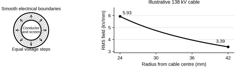
Figure 3. Calculated radial field for the illustrative 138 kV cable. Equal voltage steps occupy less distance near the conductor, where stress is greatest.
Why small defects can have large consequences
A protrusion concentrates the field at its tip. Height and tip radius matter: a taller, sharper projection produces more local enhancement than a smooth surface. A gas-filled void can also experience elevated field because its permittivity differs from the surrounding polymer; void shape and orientation affect the result. If the local conditions initiate partial discharge, repeated localized breakdown can erode insulation and promote further deterioration.
Contaminants, incomplete crosslinking, cracks, delamination and missing semiconductive material create different disturbances in the insulation system. Electrical trees and water trees are distinct degradation processes. Selecting a water-tree-resistant compound addresses an important wet-service mechanism, while preventing sharp defects and preserving interfaces remain essential to controlling electrical treeing and partial discharge.
Bonded and Strippable Insulation Screens
The screen-insulation interface has to remain sound in service and allow reliable accessory preparation. The practical choice balances dielectric performance with the risk of damaging insulation during removal. Bonded screens adhere firmly and require a qualified removal method. Strippable screens are common in North American MV distribution cable because controlled removal can simplify accessory preparation. HV and EHV extruded-insulation systems generally use bonded insulation screens.
Strippability depends on both compound formulation and processing. A suitable material can lose its intended removal characteristics if the extrusion or curing profile is unsuitable. Storage and temperature can also affect adhesion. This is a useful example of why a material designation alone does not establish the finished cable’s behaviour.
The acceptable removal force, remaining surface condition and accessory preparation method need to agree. A screen that is difficult to remove may encourage nicks or excessive working of the insulation. Residual semiconductive material or a damaged cutback can create a new local stress concentration. The practical choice combines qualified electrical performance, controlled adhesion and a preparation method that field crews can reproduce.
Metallic Screens, Sheaths and Fault-Current Performance
The choice between a shield and a concentric neutral follows the circuit’s return-current duty. The metallic layer provides the outer electrode and carries charging current, induced current and assigned fault current. A concentric neutral also provides a normal load-current return function. These different duties affect the amount of metal, losses, cost and the connections needed at joints and equipment, so a neutral and a shield are not automatically interchangeable.
On a single-phase utility lateral, neutral current can approach phase current. A three-phase feeder may permit a reduced neutral after considering unbalance, harmonics and faults. A three-wire industrial circuit may instead use a screen with a separate grounding arrangement. Required current, permissible temperature and the actual return paths determine the necessary metal capacity.
Helical copper wires, copper tapes, flat straps, corrugated metal and continuous sheaths have different flexibility, connections and current-carrying contributions. A thin tape screen does not automatically provide the required earth-fault capacity. Continuous metallic sheaths may contribute useful fault capacity as well as moisture protection, changing the amount of separate screen metal required. Those contributions must be demonstrated for the complete construction and connections.
Charging current and fault heating
A cable draws charging current whenever it is energized because its conductor and metallic screen form a capacitor. This effect becomes significant on longer transmission circuits even when little power is being delivered. With absolute insulation permittivity ε, the same radii a and b, route length L and RMS conductor-to-screen voltage Vcs, capacitance per unit length and charging current per phase are as follows. This calculation treats voltage as uniform along the route.
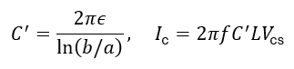
Absolute permittivity is ε = ε₀εᵣ, where ε₀ ≈ 8.854 × 10⁻¹² F/m and relative permittivity εᵣ is dimensionless. With ε and C′ in F/m, L in metres and Vcs in volts, Ic is in amperes. For the 138 kV example with εᵣ = 2.3, C′ is about 0.229 μF/km. A 5 km cable in each phase draws about 34 A of charging current per phase at 60 Hz, even without load. On long HV and EHV circuits, charging current and reactive power can therefore affect system operation.
A metallic return path needs to survive until protection clears a fault. Its heating duty depends on current squared integrated over the clearing interval. In the following expression, i(t) is instantaneous current in the path under consideration, tc is clearing time, and Ieq is its RMS equivalent over that entire interval, including any asymmetrical component.
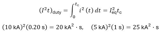
The examples give 20 and 25 kA²·s, respectively; 1 kA²·s equals 10⁶ A²·s. I²t measures heating exposure, while heat in joules also depends on electrical resistance. The lower current produces greater exposure here because it lasts longer. These figures compare duties rather than establish a cable rating. Screen or neutral area, initial temperature, permissible final temperature and fault-current split all matter. Joints, terminations and bonds must carry their assigned current too. Backup clearing and reclosing are relevant where little cooling occurs between events.
Protecting Cable Systems Against Moisture
Moisture can age insulation and corrode the metallic layers needed for fault return. Water protection therefore addresses both entry through the wall and spread along the cable after local damage. Longitudinal blocking limits that spread. Swellable tapes, yarns, powders and conductor compounds interrupt paths along strands and around metallic screens. Their location and electrical properties must suit the layers they contact; a tape between the insulation screen and metallic layer also has an electrical-interface role.
Radial barriers limit water entering through the cable wall. Copper screen wires alone do not create a continuous barrier. HV and EHV constructions can use lead-alloy sheaths, laminated aluminum barriers or continuous metallic sheaths. A laminated aluminum tape relies on its sealed overlap and bond to the jacket for continuity. Smooth welded aluminum or copper sheaths combine a continuous barrier with useful fault-current capacity; corrugation can improve flexibility. Seams, bending behaviour, fatigue resistance and the required fault contribution therefore belong in the comparison of finished constructions.
The jacket choice follows the route’s mechanical, chemical and environmental exposure. Burial or duct conditions, abrasion, cold-weather handling, chemicals, fire exposure and the need to electrically isolate a metallic sheath set the relevant requirements. Polyethylene, PVC, CPE and low-smoke halogen-free compounds serve different combinations of those needs. A jacket material name alone does not establish all of these ratings.
Water protection continues through the accessories. A sound cable barrier can be defeated by an unsuitable joint seal or jacket repair. Conversely, specified water-penetration tests and compatible seals provide evidence that the assembled system controls the intended exposure. Corrosion of metallic layers can reduce current capacity and change fault-return conditions as well as damage the cable physically.
Accessories and Bonding in the Complete Cable System
The circuit’s usable performance depends on its joints and terminations as well as the manufactured cable. A joint connects production lengths or provides a repair; a termination connects cable to equipment or an overhead interface. Each accessory recreates the relevant conductor connection, dielectric withstand, screen-current path and environmental protection. At a screen cutback, the geometry changes from the cable’s regular radial field. Stress cones or other grading elements control that transition.
Accessory compatibility includes conductor material and construction, insulation diameter and tolerances, screen preparation, neutral or sheath connections and jacket sealing. A common mating interface or matching nominal voltage does not establish all of those conditions. For HV and EHV systems, qualification of cable with its accessories is particularly important because the tested interfaces and electrical stresses form part of the design basis.
Why the bonding arrangement affects ampacity
The bonding arrangement trades additional sheath loss against standing sheath voltage, so it affects how much useful current the cable can carry. Electrical screening does not eliminate the cable’s AC magnetic field. Conductor current induces voltage along the metallic sheath. Earthing both ends closes a loop that can carry circulating current and add heat. This solid-bonding arrangement limits standing sheath voltage, but its additional loss can reduce ampacity.
Single-point bonding removes the normal closed sheath loop for the bonded section, allowing a different loss balance. It also permits standing sheath voltage toward the isolated end. Cross-bonding connects sections so induced voltages largely cancel over a major section. Section length, phase geometry and balance determine the residual voltage and loss; there is no universal route length that establishes a suitable arrangement.
Link boxes, bonding leads, sheath voltage limiters and earth-continuity paths complete the arrangement. Normal induced voltage, fault conditions, ground-potential rise and jacket withstand must be coordinated. The bond is therefore part of the electrical and thermal design, not simply a grounding detail added after cable selection.
Monitoring where it supports the operating objective
Monitoring is useful where operators need temperature or disturbance information to support loading and maintenance decisions. Selected HV land systems incorporate fibre-optic monitoring for these purposes. Distributed temperature sensing measures the sensing fibre’s temperature; a thermal model relates it to conductor temperature and current rating. Distributed acoustic sensing detects disturbances along the fibre. Fibre location, route coverage and the intended operating decision determine the useful configuration. Monitoring adds information but does not replace a sound route rating, qualified interfaces or protection.
Manufacturing Quality and Design Qualification
The design calculations assume geometry and material properties that manufacturing must reproduce. Cleanliness and process control are therefore part of dielectric performance. Clean transfer paths, controlled feeding and filtration reduce foreign particles and moisture before extrusion. Surface and dimensional measurements help confirm that the stressed interfaces match the intended design.
Triple extrusion applies the conductor screen, main insulation and insulation screen together under controlled conditions. This limits exposure between layers and helps produce continuous interfaces. Extrusion stability controls wall and concentricity. Curing develops the crosslinked polymer structure, while controlled cooling preserves geometry. For constructions that require it, degassing removes crosslinking by-products before service.
These controls address different defects. Clean compounds cannot compensate for an unstable extrusion process; a good extrusion profile cannot remove contamination introduced upstream. Incomplete curing can produce inclusions, while protrusions or locally thin regions can raise stress. As design stress increases, control of defect size and surface irregularity becomes more demanding.
A quality system also connects design to suppliers and production. Approved materials, incoming inspection, traceability, in-process checks and recorded acceptance criteria help ensure that production uses the construction that was qualified. Nonconforming material or cable must be identified and controlled before it moves to the next production stage. Investigation and corrective action address why the problem occurred, rather than only rejecting the affected length.
Design qualification and production testing answer different questions. Qualification demonstrates that a defined design and, where required, its accessory system can meet prescribed performance requirements. Routine and sample tests assess manufactured cable against the applicable acceptance criteria. Both are needed: a successful qualification does not ensure that every subsequent length is free of defects, and a production test does not substitute for the complete design-qualification programme.
Changes to compounds, suppliers, processing or interfaces need assessment against that qualification basis. Manufacturers may use different qualified formulations and processes while achieving the same specified result. The useful specification identifies required performance, dimensions, acceptance evidence and change control; it does not need to prescribe every proprietary recipe or machine setting.
Designing for Long-Term System Reliability
Cable reliability continues to depend on the same interfaces after manufacture. Installation can damage a jacket, distort a metallic layer or contaminate an accessory. Pulling tension, sidewall pressure, bend radius and twisting must remain compatible with the offered construction. Cable and accessory preparation must preserve the surfaces on which electrical stress control depends. These installation constraints belong in the design information supplied with the cable.
The magnetic field also creates forces between phase cables. During a short circuit, peak current can produce rapid movement unless the cleats and supports restrain it. Thermal expansion creates a different mechanical duty, especially near terminations. The installed arrangement must accommodate both fault forces and normal expansion without transferring damaging loads into accessories. A cable’s thermal fault rating alone does not establish the restraint system’s mechanical performance.
Heat, load history and repeated exposure
Ampacity ultimately depends on keeping temperature within the system’s operating limits. Heat accelerates polymer ageing and can reduce flexibility and dielectric performance. The conductor, metallic layers and dielectric generate heat that must pass through the cable and the surrounding route. A poor connection can create a local hot spot even when the cable’s average loading appears acceptable.
For radial heat flow through a uniform insulation annulus with constant thermal conductivity, the layer’s thermal resistance parameter Tins is given below. Radii a and b use the same units; thermal conductivity kth is in W/(m·K), giving Tins in K·m/W.
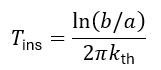
In the 138 kV example, keeping a at 24 mm and increasing the insulation wall from 18 to 24 mm changes b from 42 to 48 mm. At the same RMS voltage, the largest field falls from 5.93 to 4.79 kV/mm. With thermal conductivity unchanged, this layer’s thermal resistance increases by 23.9%, or about 24%. More insulation also affects accessory dimensions. The resulting ampacity depends on the complete cable and route.
Dielectric heating persists whenever the cable is energized, including at little load. With capacitance C′ in F/m, frequency f in Hz and RMS Vcs in volts, loss wd is in W/m per phase. The loss tangent tan δ is a dimensionless ratio: for example, a reported 0.1% enters the equation as 0.001.
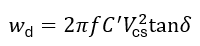
The voltage-squared relationship helps explain the importance of low dielectric loss at HV and EHV. The complete heat path includes metallic losses, jacket, ducts, backfill, soil, ambient temperature and nearby circuits. A current rating without those conditions is incomplete.
Duty describes the cable’s service exposures; duty cycle describes their time pattern. The peak load, its duration, earlier loading and cooling time affect temperature. Emergency loading also depends on the initial thermal condition and allowed duration. Repeated expansion, contraction, faults and switching events add to the exposure history. Magnitude, duration and recurrence belong together when defining the service the cable must withstand.
Testing and useful acceptance evidence
A specified design still needs evidence that it has been manufactured and installed correctly. Factory qualification, production tests and field acceptance have different purposes. Field testing assesses the installed system, including interfaces created on site. A withstand test establishes performance under its applied duty; diagnostic measurements provide different information about defects and condition. Neither a single passing test nor one diagnostic value establishes remaining service life. The test objective, cable condition and required acceptance evidence must agree.
A specification that supports several qualified manufacturers
A useful specification gives competing manufacturers the same operating conditions, required performance and acceptance criteria. This creates a common basis for comparing cost and demonstrating suitability. The cable layers, qualification and production requirements then support that objective. Each restriction needs an electrical, environmental, installation or maintenance reason. Reviewing inherited requirements with cable specialists can expose added cost or incompatibility that has survived successive specification revisions.
Utilities can standardize cable families across approved manufacturers to reduce spare cable, elbows, splices, connectors, tools and training requirements. That benefit depends on controlled conductor interfaces, insulation-diameter ranges, screen preparation and jacket or neutral connections. A change from TR-XLPE to EPR, or to another screen construction, can alter dimensions and preparation even at the same nominal kV and conductor size.
Several manufacturers can meet common operational interfaces while retaining their own qualified compounds and processes. The approved accessory and repair combinations, dimensional tolerances, traceability and change control protect interchangeability. Understanding the cable’s construction makes these requirements easier to justify and allows cost, reliability and service life to be evaluated together.
